15min read
The concrete pavement is generally the most important aspect of an industrial project to a client but often has the least amount of design and is the least understood by design engineers.
It is likely to be the most costly item in terms of maintenance through the life of the building but these costs can be greatly reduced by engineers gaining an understanding of the material and the logical set-out and detailing of joints.
The purpose of this article is to de-mystify the characteristics and behaviours of concrete pavements in order to give designers enough insight to make rational design choices in producing economical low-maintenance designs.
Introduction
There is a general view amongst design engineers that the behaviour of concrete pavement slabs is difficult to predict and cracking is impossible to avoid. Whilst there is a grain of truth to this due to the number of variables involved in the behaviour of concrete pavements it is by no means an excuse for cracking and maintenance costs which should have been avoided by better design and detailing. Studies undertaken on heavily trafficked concrete road surfaces show that a well-designed and constructed concrete pavement incur less than 10% of the maintenance costs per square metre than a poorly designed and constructed pavement. Add to this the costs due to damage to equipment (particularly hard forklift wheels), possible spine injuries to personnel and trip hazards caused by poor joint detailing and it becomes clear why a pavement slab needs adequate care and attention in design.
The moniker ‘Plain Concrete’ when considering pavements refers not only to concrete lacking any kind of reinforcement but also concrete with low levels of reinforcement intended primarily to aid in the control of cracking. There are a great number of points to consider when designing such pavements and to list them all here would be exhaustive, particularly since there are excellent resources available such as the CCAA T48 – Guide to Industrial Floors and Pavements which has an 18 step design procedure. Every engineer specifying pavements should make themselves familiar with this document.
A well-designed concrete pavement is the finished surface, or base, of the pavement system and it’s thickness is primarily determined based upon the combined stiffness and depth of the sub-base (typically crushed rock) and the sub-grade (the natural or prepared soil between the sub-base and the underlying rock) required to remain serviceable for a determined design-life under a predicted loading regime. Even a well-designed pavement constructed to the correct grade and properly mixed, vibrated and cured will crack and become unserviceable if inadequate control against shrinkage cracking is provided.
How Pavements Shrink
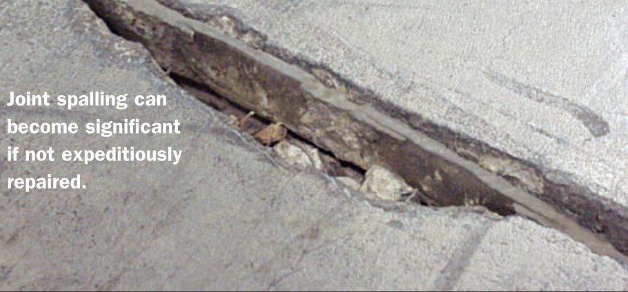
As concrete cures, it undergoes chemical changes and loses capillary water causing it to reduce in size. At the same time, it is gaining structural strength due to the chemical bonds which are forming between its constituent materials. If at any point during this process a strain occurs due to the shrinkage being resisted by forces which exceed the increasing tensile or shear strength of the concrete a brittle failure will occur and a crack will form. Small cracks may remain un-noticed and can have no detrimental effect to the performance of the pavement. Larger cracks, as well as being visually unappealing, may affect the structural performance of the pavement and be further damaged, particularly by heavily loaded wheels in heavily trafficked areas. In extreme cases a large damaged crack can cause a trip hazard, damage to wheels, jolts when driven over which lead to injury and litigation, as well as giving access to the sub-base which can be degraded by water and mechanical action, and a breakdown in a seal which can compromise sanitation in food processing plants.
Controlling Shrinkage
Well-designed concrete pavements are divided by joints into individual panels as an attempt to separate the full shrinkage of a large area of concrete amongst a number of smaller, ideally square panels, whilst maintaining the ability of the pavement to transfer vertical shear loads between panels, i.e. a slab panel carrying a loaded wheel should be able to share this load to an adjacent panel.
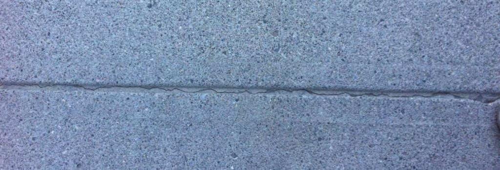
Joints within a single concrete pour which facilitate the differential shrinkage between panels are typically referred to as ‘contraction joints’ and the goal of contraction joint design and construction is to form a line of weakness where the early structural strength of the concrete is exceeded thus forming a ‘controlled’ crack before the early strength can be exceeded at any other location in the panel. In its most common form this consists of a ‘saw-cut joint’ where a 3-5mm saw is used to cut the surface of the concrete, typically extending 1/3 of the depth of the base, at an early enough stage of curing that no cracks have yet formed, but enough strength has formed to provide a working platform for the sawing.
The timing of saw-cutting joints is critical because cutting too early can damage the surface whilst cutting too late can mean the slab has formed panels by means of ‘uncontrolled’ cracks at arbitrary locations where the tensile strength has been exceeded, and thus the new saw-cut joints are useless. Since the speed of curing varies depending on a variety of factors the ideal timing can vary from anything between 4 hours to 24 hours after pouring.
The goal of contraction joint design and construction is to form a weakness where the early structural strength of the concrete is exceeded thus forming a ‘controlled’ crack before the early strength can be exceeded at any other location in the panel
A square panel will attempt to shrink towards is geometric centre and in ideal uniform environment each of the 8 edges will shrink an identical length toward the centre. Ideal situations however are almost impossible since various factors control how the concrete shrinks. Some important factors are discussed here;
Curling
The amount and timing of shrinkage is not uniform throughout the pavement; the bottom of the slab retains more capillary moisture than the top surface and so shrinks less and at a slower rate than the top surface. This causes a phenomenon called ‘curling’. Strains are locked into the slab as it attempts to lift its sides and corners in opposition to its weight. The larger the slab panel the more pronounced the effect.
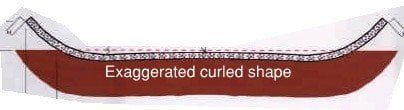
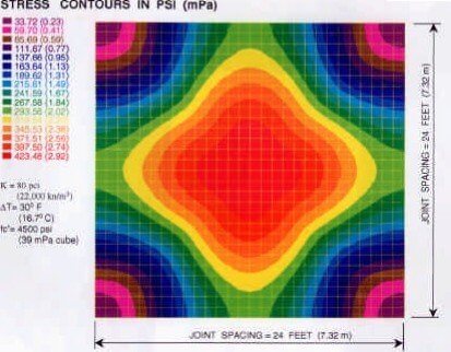
At its worst, in wetted areas, curling can cause corners and edges to lift away from the sub-base, and can combine with damaged/poorly sealed joints, and ‘pumping’ hydraulic action of vehicle wheels to form voids under joints as more sub-base material is removed. The designer should also be aware that a level of tensile stress will be present in the surface of a pavement due to the resistance to curling which plays a role in the formation of un- controlled cracking. These problems are best mitigated by avoiding large individual slab panels.
Base Friction
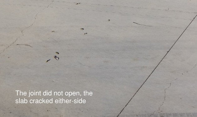
Linear shrinkage of a slab is resisted by friction on the underside of the base. This friction is a result of the concrete weight and friction coefficient of the interacting materials but also by the non- uniformity of the concrete and/or sub-base material at this junction. If the level of friction is not uniform areas of the base can essentially become ‘locked’ to the sub-base. Instead of shrinking toward the geometric centre of individual panels the slabs can instead attempt to shrink toward the ‘locked’ zone. Saw-cut joints in a ‘locked’ zone may not open at all but adjacent panels may open twice as wide to compensate or the panels affected may crack at an uncontrolled location as stresses exceed the structural stress limit away from a saw-cut joint.
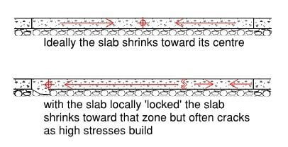
Often two layers of poly membrane are specified and a thin layer of fine bedding sand in an attempt to ensure a low-friction plane for sliding, but care must also be taken on-site to ensure the surface is level and free from obvious imperfections.
Connections to Structure
Structural items like walls and columns can restrain slab panels forcing the panel to shrink towards this location. Without care this can cause the same cracking and lack of joint uniformity discussed above due to ‘locked’ zones. Engineers must also be aware that non-structural items such as bollards or sign-poles can cause the same effect.
Generally structural columns and walls are ‘isolated’ from the concrete pavement by using joints to allow movement or by forming pockets where columns penetrate a pavement panel. Locating a column in the centre of a slab panel without an isolating pocket may not cause any cracking since it is at the ideal centre of shrinkage.
How a Crack Becomes a Problem
Concrete is not a perfectly uniform material and so cracks do not form in perfectly uniform planes. A typical uncontrolled crack forms a jagged line on the surface of a slab but if this line was followed to the base of the slab it would follow some arbitrary line of weakness until it reaches the base where it would form a different jagged pattern to that on the surface. Load as light as foot-traffic can then damage the very sharp edges formed causing material to easily crack away leaving a much larger width at the surface than the main body of the crack. Well-controlled cracks however are typically initiated at the surface by saw-cuts or formed grooves giving reasonably uniform straight edges which are more difficult to damage, thus a controlled-crack is always preferable to an un-controlled crack.
A controlled-crack is always preferable to an un-controlled crack
Beneath the surface of a crack in a plain un-dowelled concrete pavement aggregate each side of the crack maintains some level of interlock, like the teeth of two cogs in a machine, thus transferring the loading from one side of the crack to the other. As a crack grows the separation increases so this level of interlock reduces, and with it the ability of the slab to transfer loads. T48 quotes results of research showing that where an opening of 0.6mm has formed aggregate interlock is essentially 100% effective at transferring shear force across a joint. At 0.9mm the effectiveness reduces to 60%, and an increase to a gap of around 1.5mm yields a crack able to transfer only 15% of the shear force. At 2mm the load transfer is described as ‘minimal’.
According to AS3600 (table 3.1.7.2) 200mm of 25MPa thick concrete will have 660 microstrain due to shrinkage after 30 years in an interior environment. If we conservatively estimate that base- friction and a damp sub-base limit this to approximately 400 microstrain of effective shrinkage for a slab-on-ground the amount of shrinkage for a 3.75m wide pavement panel would be 1.5mm, Typical Australian industrial pavements are detailed with slab panels ranging from 4.5m dimensions up-to around 6.0m. How is the load being effectively transferred across these joints?
Dowelled Joints
When it is recognised that aggregate interlock alone will not be sufficient to transfer the design loading across a joint the slab can locally be made deeper each side of the joint and designed as an ‘end-condition’ according to T48. A more common alternative though is to provide dowels in the form of steel bars or plates at a specified spacing which extend across the width of the opening and work in almost pure-shear to transfer the load across a joint. Dowels are designed to account for the largest likely load (considering load shear between a numbers of dowels due to stiffness of the pavement) which generally comes from a heavily loaded wheel or racking support post. An inadequate dowel design can mean a punching shear failure across a joint and a very expensive fix.
As well as providing load transfer dowels should allow the connected slab panels to shrink away toward their geometric centre. This movement may not necessarily be in the same direction as the dowel is aligned, thus it is important that dowels allow an amount of movement in a secondary dimension. There are numerous proprietary jointing systems which achieve this in different ways. Commonly used types include square dowel bars which have a deformable plastic box and diamond-shaped and tapered plate dowels which by the nature of their geometry inherently allow 2-dimensional movement.
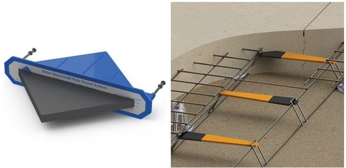
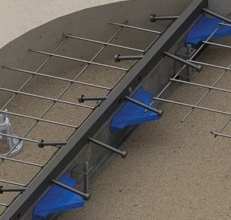
Dowels also allow some movement in a third dimension, i.e. up- down, before load is fully transferred. Movement of upto 3mm is inherent in dowel systems with a crushable plastic box, but dowel systems such as Danley PD3 tapered plates have a thin plastic sheath allowing less than 1mm. 3mm may be appropriate where pneumatic wheels, foot-traffic or stationary post loads are dominant, but the great enemy of industrial floors are heavily loaded hard-wheeled forklifts which can initiate joint damage across a joint with only 1mm or so height differential. In these cases it is preferable to specify reinforced joint edges, proprietary systems are available to provide this. It is important that these factors are discussed with the Client during design as the pavement and its reinforcement are likely to be amongst the most costly components of the project.
Conclusion
Concrete pavements are not an uncontrollable animal, but like an uncontrollable animal they can cause a lot of damage, pain and expense when allowed to run wild.
For design engineers there are of course factors outside of our control which affect the behaviour of concrete pavements but it is critical that we apply our expertise fully in design and assess all the factors which are in our control because many of the failures commonly seen in-practice can be easily avoided in design.
This is by no means a full account of the behaviour of concrete pavements, in many areas I have not even scratched the surface, however it is my hope that in this short paper I have given the reader some fresh insight and understanding to the behaviour of industrial concrete pavements and encouraged application of the correct amount of thought and logic to their design. Industrial pavements are simply heavily loaded and trafficked pavements, thus the same logic and thought can be applied to any concrete pavement on ground.